Power Plan Electricity
In generating electrical energy, apart from producing electricity which is used by various consumers, it also uses the generated electrical energy for various purposes itself. These systems include the Draft System, Feedwater system, fuel system, and many others.
Combustion of fossil fuels or nuclear aims to convert the potential energy contained therein into heat energy in water vapor, which is then used to rotate the blades of steam turbines to produce mechanical energy. In a jet turbine, water vapor media is not used so that the combustion of fuel oil which produces heat energy is directly used to rotate the blades of the steam turbine and produce rotating energy. Meanwhile, power plants that use other potential energy sources such as wind, waterfalls and geothermal, have principles that are not much different from one another. Furthermore, the mechanical energy that can be derived from the various energy sources above is converted into electrical energy using an electric generator.
A power plant operates with the aim of producing electrical energy which is then distributed to various consumers. As a potential energy source, fossil fuels such as diesel (HSD), coal, potential energy from water, wind, geothermal, or nuclear reactions can be used.
Ohm’s Law
One theory on which all electrical laws are based is Ohm’s Law. Ohm’s Law simply states that the amount of current (Ampere) flowing in an electric circuit is equal to the ratio between the electromotive force (Volts) flowing, to the resistance (Ohm) of the circuit.
I = E / R
Where:
I = Electric current in amperes
E = Electromotive force in volts
R = Resistance in ohms
Kirchhoff Law’s
Kirchhoff’s law explains that the algebraic sum of all electric currents flowing in and out at a given point in an electrical circuit must add up to zero. This is in principle consistent with the law of conservation of mass. On the voltage side, this law explains that the sum of all electromotive forces in an electric circuit with a potential difference (voltage drop) is also zero. This is also synonymous with the principle of conservation of energy.
Power
Power is the level of doing work. In the world of electricity, power is the product of voltage and current, and can be represented by several equations:
P = E x I
P = I2 x R
P = E2 / R
Where,
P = Power in watt
I = Electric current in amperes
E = Electromotive force in volts
R = Resisntace in ohm
Electricity in the power plant uses a three-phase mode. The voltage and current in each phase form an angle of 120o. So that the power calculation formula in each phase becomes:
P = Cos 120° x E x I x cos Ø
P = (1/3)(31/2)> x E x I x cos Ø
So that the total power values of all phases are:
P = (31/2)> x E x I x cos Ø
Where
cos Ø called the power factor, is the cosine of the angle between the voltage wave and the current wave in single phase.
The relationship that occurs between the components of the above equation is shown in the diagram below.
AC Electrical Power Diagram
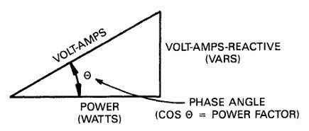
The slanted side of the triangle on the side is called total power or volt-amps, the vertical side is called reactive power / VARS, which stands for volt-amps-reactive, and for the horizontal side is active power (watts).
In a simple AC electrical system, it is composed of electrical sources and loads in the form of sinusoidal currents and voltages. Electrical loads can be resistive, inductive, and capacitive. In purely resistive loads, the polarity of the source and the electric load reverses at the same time. At any given time, the product of current and voltage is positive, which indicates that no energy flow has been returned. In this case, there is only real force at work.
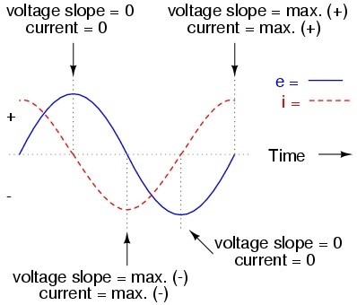
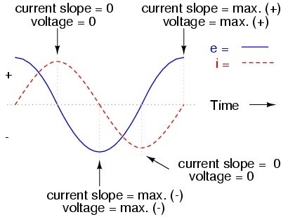
In a purely reactive electric load, the voltage and current have a phase distance of 90 °. Where the capacitive load rated current is 90 ° behind the voltage, while the inductive load current is 90 ° ahead of the voltage. Half of each cycle of reactive load, the product of the voltage and current is positive, and the other half is negative, this indicates that the average energy flowing towards the load is exactly the same as the value it reversed. In this case only reactive energy flows, and no total energy flows to the load.
Capacitive Reactive
Inductive Reactive
In actual fact, the electric load is a combination of resistive, conductive, and capacitive loads, so that reactive power and active power flow together towards the real load. Here it is determined that the total power (apparent power) is the sum of the vectors between active power and reactive power. Apparent power is of great concern in electricity generation, this is because the nature of reactive power that does not work directly against the load, it creates heat in the cable line, and is detrimental. This requires special handling using large capacitors, transformers, and a system in the generator to compensate for the reactive power.

